
Arduino WiFi IMU Angles (6 Steps)
This article covers how to calculate the IMU (Inertial Measurement Unit) angles of an Arduino UNO WiFi Rev2 microcontroller.
In my previous article (How to Read an Arduino UNO WiFi IMU) I covered how to read raw data from the IMU by creating a class. In this article I'm going to show you how to extend that class to calculate roll, pitch and yaw values.
This is part of my free mini-course: How to Build an Arduino UNO Robot. Which I'm making available as a series of blog posts.
Step 1. Clone the previous sketch
This step assumes that you've gone through the previous article. If you don't have the previous code available, I'll provide the complete listing for each modified file below.
- Open up the Arduino editor at: https://create.arduino.cc/editor/
- Duplicate the previous sketch (
desertbot_MonitorIMU_test) by making a copy calleddesertbot_MonitorIMU_Angles_test.
Step 2. Modify the header file
In this step we need to define one new property and two new methods to be added to the desertbot_MonitorIMU class.
To do that we first need to add their prototypes to the header file:
- Edit the file (tab) desertbot_MonitorIMU.h
- Add this to the header below the other include statement:
#include <MadgwickAHRS.h>
- Add a filter property below the spacer property in the class definition:
Madgwick filter;
- Add new public methods to the class header:
void monitorAngle(const char * label, float value);
void angleLoop();
Final desertbot_MonitorIMU.h listing
After the modifications, your code should look like this:
/*
 * Author: Mitch Allen
 * File: desertbot_MonitorIMU.h
 * Web Site: https://desertbot.io
 */

#ifndef desertbot_MonitorIMU_h
#define desertbot_MonitorIMU_h

#include <Arduino_LSM6DS3.h>
// new include
#include <MadgwickAHRS.h>

class desertbot_MonitorIMU {
  public:
    int delayMs;
    const char * spacer;
    Madgwick filter;
    desertbot_MonitorIMU();
    void monitor(const char * message);
    void monitorFloat(float value);
    void init();
    void debugLoop();
    // new methods
    void monitorAngle(const char * label, float value);
    void angleLoop();
};

#endif
Code Description
- The Madgwick filter is a library for calculating roll, pitch and yaw values from raw IMU data
- The monitorAngle method will be used to write roll, pitch and yaw values to the serial monitor
- The angleLoop method is similar to the debugLoop defined in the previous article
- But instead of logging raw data, the method will calculate and log roll, pitch and yaw values
I'll explain how those methods are implemented below.
Step 3. Modify the class file
Now that the new methods have been defined in the header, they need to be added to the class file.
- Edit the file (tab) desertbot_MonitorIMU.cpp
- Add this below the include statement:
#define MONITOR_SAMPLE_RATE 10
This value will be used by the filter to set the sample rate (in Hz).
- Add this line to the bottom of the init method:
filter.begin(MONITOR_SAMPLE_RATE);
The init method has been modified to initiate the new filter with the new sample rate.
- Add the monitorAngle method that was prototyped in the header to the class
- The method name, return type and arguments must match what you put in the header:
void desertbot_MonitorIMU::monitorAngle(const char * label, float value)
{
  char buffer[5];
  Serial.print(label);
  Serial.print(dtostrf(value, 4, 0, buffer));
  Serial.print(spacer);
}
The monitorAngle method is similar to the monitorFloat method.
It's a method to simplify writing labeled values (like roll, pitch and yaw) to the monitor.
- Add the angleLoop method that was prototyped in the header to the class:
void desertbot_MonitorIMU::angleLoop()
{
  float aX, aY, aZ;
  float gX, gY, gZ;

  if (
    IMU.accelerationAvailable()
    && IMU.gyroscopeAvailable()
  ) {
      IMU.readAcceleration(aX, aY, aZ);
      IMU.readGyroscope(gX, gY, gZ);

      filter.updateIMU(gX, gY, gZ, aX, aY, aZ);

      monitorAngle("Roll: ", filter.getRoll());
      monitorAngle("Pitch: ", filter.getPitch());
      monitorAngle("Yaw: ", filter.getYaw());

      Serial.println("");
  }
}
The angleLoop method is similar to the debugLoop method defined previously.
But this time the acceleration and gyroscope data is passed to the filter.
Then the filter getRoll, getPitch and getYaw methods are called to calculate their respective values.
The values are then passed to the new monitorAngle method for logging to the serial monitor.
Final desertbot_MonitorIMU.cpp listing
The complete code listing should now look like this:
/*
 * Author: Mitch Allen
 * File: desertbot_MonitorIMU.cpp
 * Web Site: https://desertbot.io
 */

#include "desertbot_MonitorIMU.h"

// new define
#define MONITOR_SAMPLE_RATE 10

desertbot_MonitorIMU::desertbot_MonitorIMU()
{
  // constructor
  delayMs = 1000; // 1000ms = 1 second
  spacer = ", ";
}

void desertbot_MonitorIMU::monitor(const char * message)
{
  Serial.print("[desertbot_MonitorIMU]: ");
  Serial.println(message);
}

void desertbot_MonitorIMU::monitorFloat(float value)
{
  Serial.print(value);
  Serial.print(spacer);
}

void desertbot_MonitorIMU::init()
{
  if (!IMU.begin()) {
    monitor("Failed to initialize IMU!");
    while (true); // halt program
  }
  monitor("IMU initialized!");
  // new call to filter.begin
  filter.begin(MONITOR_SAMPLE_RATE);
}

void desertbot_MonitorIMU::debugLoop()
{
  float aX, aY, aZ;
  float gX, gY, gZ;

  if (
    IMU.accelerationAvailable()
    && IMU.gyroscopeAvailable()
  ) {
      IMU.readAcceleration(aX, aY, aZ);
      IMU.readGyroscope(gX, gY, gZ);
      monitorFloat(aX);
      monitorFloat(aY);
      monitorFloat(aZ);
      monitorFloat(gX);
      monitorFloat(gY);
      Serial.println(gZ);
      delay(delayMs);
  }
}

// New methods

void desertbot_MonitorIMU::monitorAngle(const char * label, float value)
{
  char buffer[5];
  Serial.print(label);
  Serial.print(dtostrf(value, 4, 0, buffer));
  Serial.print(spacer);
}

void desertbot_MonitorIMU::angleLoop()
{
  float aX, aY, aZ;
  float gX, gY, gZ;

  if (
    IMU.accelerationAvailable()
    && IMU.gyroscopeAvailable()
  ) {
      IMU.readAcceleration(aX, aY, aZ);
      IMU.readGyroscope(gX, gY, gZ);

      filter.updateIMU(gX, gY, gZ, aX, aY, aZ);

      monitorAngle("Roll: ", filter.getRoll());
      monitorAngle("Pitch: ", filter.getPitch());
      monitorAngle("Yaw: ", filter.getYaw());

      Serial.println("");
  }
}
Step 4. Modify the test / example code
Now that the class has been modified, add some code to the main file to test it with the new method.
- Edit the first file in the sketch (desertbot_MonitorIMU_Angle_test)
- Add this #define under the include statement:
// new sample rate
#define SAMPLE_RATE 10
This value should match the sample rate used in the class init method.
- Modify the loop:
void loop() {
  // imuMonitor.debugLoop();
  // new loop
  static unsigned long previousTime = millis();
  unsigned long currentTime = millis();
  if (currentTime - previousTime >= 1000 / SAMPLE_RATE) {
    imuMonitor.angleLoop();
    previousTime = millis();
   }
}
This modified loop method comments out the original debugLoop call (still handy incase we want to debug later).
The code uses a standard Arduino coding technique to only call a function at a set interval.
The method called within the loop is the new angleLoop method to log the roll, pitch and yaw.
Final desertbot_MonitorIMU_Angles_test listing
After the edits, the code should look like this:
/*
 * Author: Mitch Allen
 * File: desertbot_MonitorIMU_Angles_test
 * Web Site: https://desertbot.io
 */

#include "desertbot_MonitorIMU.h"

// new sample rate
#define SAMPLE_RATE 10

desertbot_MonitorIMU imuMonitor = desertbot_MonitorIMU();

void setup() {
  Serial.begin(9600);
  while (!Serial) {
    ; // wait for serial port to connect. Needed for native USB port only
  }
  imuMonitor.delayMs = 1500;
  imuMonitor.spacer = " | ";
  imuMonitor.init();
}

void loop() {
  // imuMonitor.debugLoop();
  // new loop
  static unsigned long previousTime = millis();
  unsigned long currentTime = millis();
  if (currentTime - previousTime >= 1000 / SAMPLE_RATE) {
    imuMonitor.angleLoop();
    previousTime = millis();
   }
}
Step 5. Upload the code to the board
Now that all of the code has been modified, it's time to upload it to the board.
- Above the edit window, search for Arduino Uno WiFi Rev2
- Click the Upload and Save (arrow) button
- You may see some errors fly by at the bottom of the screen
- If the uploading ends with a green Success message the upload was successful
Step 6. Test the code while tethered
To test the IMU do the following:
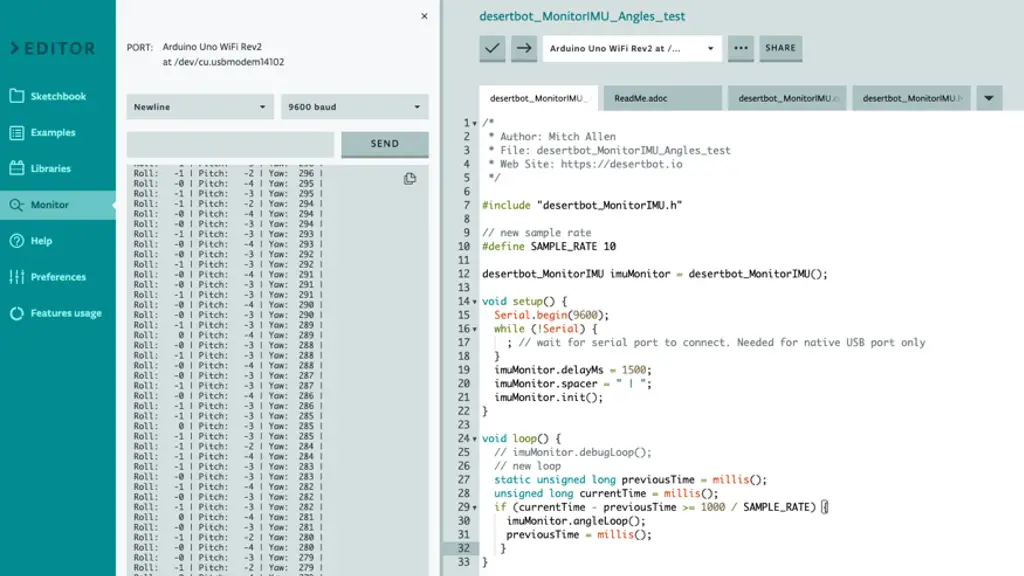
- In the Arduino Web IDE click the Monitor button in the tool bar
- Don't worry if you see a message containing port unavailable - it takes a moment to connect
Once the monitor connects, you should see lines of data like this fly by:
[desertbot_MonitorIMU]: IMU initialized!
Roll:    0 | Pitch:   -2 | Yaw:  180 |
Roll:    0 | Pitch:   -3 | Yaw:  179 |
Roll:    0 | Pitch:   -2 | Yaw:  179 |
Roll:    1 | Pitch:   -4 | Yaw:  178 |
Roll:    0 | Pitch:   -3 | Yaw:  178 |
Roll:    0 | Pitch:   -2 | Yaw:  177 |
Roll:    1 | Pitch:   -4 | Yaw:  177 |
Roll:    0 | Pitch:   -3 | Yaw:  177 |
Roll:   -0 | Pitch:   -2 | Yaw:  176 |
Roll:    1 | Pitch:   -3 | Yaw:  176 |
Roll:    0 | Pitch:   -3 | Yaw:  175 |
To monitor the values live, click the AUTOSCROLL checkbox at the bottom of the monitor.
Test roll, pitch and yaw
- While still tethered, move the robot around in space to see how the values for roll, pitch and yaw change
- Roll the robot left and right:
- When the robot is flat the roll value should be around zero
- When you roll one way the value rises above zero
- When you roll the other way the value becomes negative and moves lower, away from zero
- Pitch the robot up and down:
- When the robot is flat the pitch value should be around zero
- When you pitch the robot in one direction the value rises above zero
- When you pitch the robot in the other direction the value becomes negative and moves lower, away from zero
- Turn the robot left and right to test the yaw value:
- When you turn the robot counter-clockwise the value increases
- If the value exceeds 360 it will wrap back to 0 and continue to increase as you turn the robot
- When you turn the robot clockwise the value decreases
- If the value falls below zero it will wrap to 360 and continue to decrease as you turn the robot
Why do the numbers change even if the board isn't moving?
The data isn't perfect and is a bit noisy. But if the robot is stationary they shouldn't change too much.
Troubleshooting
Compiler errors
If the code won't compile, look at the compiler error and see if you can spot the problem.
Common problems are:
- missing semi-colon at the end of a statement
- missing closing curly bracket
- variable not spelled correctly
- wrong board or port configuration
If it's still not working, compare your code to the complete listing above.
Monitor just shows the fail message
If the monitor shows a fail message then you could be using a different board or the wrong library.
Because of the include this code will only work with a board that has LSM6DS3 IMU.
Monitor not working
When you first fire up the monitor or reload the program, the monitor will temporarily display a message about port unavailble. This is normal until the board connects. If it lasts more than a minute, you may have a port configuration problem. Or the board isn't connected.
Can't connect to the board
If you rebooted your Mac or PC while the board was plugged in, you may need to unplug it, then plug it back in. Then it should work.
If you still have trouble, check the cable.
Conclusion
In this article you learned how to do the following:
- Modify a class in the Arduino IDE
- Convert raw IMU data into useful roll, pitch and yaw values
- Monitor changes to the roll, pitch and yaw values live
This is an object-oriented version of code that I wrote for an Arduino 33 IOT. That board has the same IMU chip as the Arduino Uno WiFi Rev2. See: How to Read an Arduino Nano 33 IOT IMU for the original code.
Related Articles
- How to Read an Arduino UNO WiFi IMU
- How to Build an Arduino UNO Robot (Free Course)
- How to Read an Arduino Nano 33 IOT IMU
- Arduino Resource Guide