
How to Read an Arduino UNO WiFi IMU (7 Steps)
This article covers how to read the IMU (Inertial Measurement Unit) of an Arduino UNO WiFi Rev2 microcontroller.
The can be used on its own. But it's also part of my free course: How to Build an Arduino UNO Robot. Which I'm making available as a series of blog posts.
Step 1. Gather the parts
If you've been following along in the free course, you can just plug in the robot. Otherwise you can use the parts listed below:
| Description | Product Link |
|---|---|
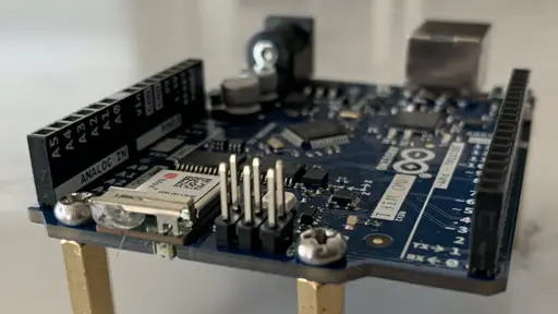
| Arduino Uno Wifi R2 | Arduino UNO WiFi REV2 [ABX00021] |
| USB-A cable | AmazonBasics USB 2.0 Printer Cable - A-Male to B-Male Cord - 6 Feet (1.8 Meters), Black |
| USB-C cable | CableCreation USB C Printer Cable 6.6ft, USB C to USB B 2.0 Cable, Compatible with MacBook Pro, HP, Canon, Brother, Samsung Printers etc, 2M/Black PVC with Aluminum Shell |
Step 2. Create a new sketch
For working with the Arduino Uno WiFi Rev2 I've found it easer to use the Web editor.
Open up the editor at:
If you've never worked with the Web IDE before you will need to signup. You will be prompted when you select an Arduino board to install a plugin. That is so the IDE can upload to and monitor the board.
Create a new sketch.
If you want to follow along with my exact steps, rename the sketch to:
desertbot_MonitorIMU_test
Step 3. Add a header file
Behind the scenes standard Arduino files follow the C++ syntax.
C++ uses header files that can be included in programs to specify what a class looks like.
In other words, what properties and methods on the class are available for use.
Next to the sketch title in the Web editor you will see a drop down:
- Click the dropdown
- Click Add Tab
- A tab in the editor is like adding a new file
- Click on the tab for the new file
- Click the dropdown again
- Click the Rename option
- Rename the file (tab) desertbot_MonitorIMU.h
Paste in this code:
/*
 * Author: Mitch Allen
 * Web Site: https://desertbot.io
 */

#ifndef desertbot_MonitorIMU_h
#define desertbot_MonitorIMU_h

#include <Arduino_LSM6DS3.h>

class desertbot_MonitorIMU {
  public:
    int delayMs;
    const char * spacer;
    desertbot_MonitorIMU();
    void monitor(const char * message);
    void monitorFloat(float value);
    void init();
    void debugLoop();
};

#endif
Code Description
ifndef wrapper
First you will notice that the class definition is wrapped like this:
#ifndef desertbot_MonitorIMU_h
#define desertbot_MonitorIMU_h

class desertbot_MonitorIMU { ... }

#endif
In theory that's supposed to keep the header from being loaded twice, if it's included in a second file. That normally works in C++. But here, if you so much as define a default value (like int delayMs = 2000) or even a constant above the class definition, that switches how the compiler interprets the header. So it pulls it in twice, and throws an error.
So don't define any default values or constants in the header to avoid errors.
Include IMU library header
This line includes the library for the Arduino Uno WiFi's built in LSM6DS3 IMU chip.
#include <Arduino_LSM6DS3.h>
Class definition
- A class called desertbot_MonitorIMU is defined
- this class has no private properties
- public properties and methods can be accessed externally - as you will see soon
The public properties for monitoring the IMU are:
int delayMs;- a delay setting to be used within the class- defined in milliseconds (1000ms = 1 second)
- used later in the code to determine how often the IMU is polled for data
const char * spacer;- a fragment of text used to delimit data printed to the monitor- the default is
", "to comma delimit the IMU variables printed to each line
- the default is
Methods
In object-oriented programming, methods are what you call functions that are part of a class.
desertbot_MonitorIMU();- the constructor- in C++ the constructor has the same name as the class
- when a program "instantiates" (creates) an instance of a class, the constructor is called to setup values, call setup methods, etc.
void init();- the constructor is fine for setting up default values (delayMs, spacer, etc), but sometimes you need to wait before calling setup methods- the downside is that you need to remember to call the init method first or the other methods won't work properly
void debugLoop();- a method to be called from in your program's loop function to print the latest IMU data to the serial monitormonitor(const char * message);- a method to print a message line to the serial monitor, prefaced with the name of the class library sending the linemonitorFloat(float value)- a method to append values (like IMU values) to a line sent to the monitor- values are delimited with the spacer string
Step 4. Add a class file
Now that the properties and methods have been defined in the header, it's time to implement them.
- Click the dropdown
- Click Add Tab
- Click on the tab for the new file
- Click the dropdown again
- Click the Rename option
- Rename the file (tab) desertbot_MonitorIMU.cpp
Paste in this code:
/*
 * Author: Mitch Allen
 * Web Site: https://desertbot.io
 */

#include "desertbot_MonitorIMU.h"

desertbot_MonitorIMU::desertbot_MonitorIMU()
{
  // constructor
  delayMs = 1000; // 1000ms = 1 second
  spacer = ", ";
}

void desertbot_MonitorIMU::monitor(const char * message)
{
  Serial.print("[desertbot_MonitorIMU]: ");
  Serial.println(message);
}

void desertbot_MonitorIMU::monitorFloat(float value)
{
  Serial.print(value);
  Serial.print(spacer);
}

void desertbot_MonitorIMU::init()
{
  if (!IMU.begin()) {
    monitor("Failed to initialize IMU!");
    while (true); // halt program
  }
  monitor("IMU initialized!");
}

void desertbot_MonitorIMU::debugLoop()
{
  float aX, aY, aZ;
  float gX, gY, gZ;

  if (
    IMU.accelerationAvailable()
    && IMU.gyroscopeAvailable()
  ) {
      IMU.readAcceleration(aX, aY, aZ);
      IMU.readGyroscope(gX, gY, gZ);
      monitorFloat(aX);
      monitorFloat(aY);
      monitorFloat(aZ);
      monitorFloat(gX);
      monitorFloat(gY);
      Serial.println(gZ);
      delay(delayMs);
  }
}
Code Description
desertbot_MonitorIMU()
In the constructor you can set the default values for delayMs and spacer.
init()
The constructor is fine for setting up default values (delayMs, spacer, etc). But if you call the functions to initialize and setup the IMU in the constructor it may not be ready yet.
You need to wait and make the function calls later from a method. The method should be called in your main Arduino files setup function.
It also gives a chance to redefine the delayMs and spacer values before the initialization methods are called. You will see an example later when I show how to use the class in a program.
The downside is that you need to remember to call the init method first or the other methods won't work properly. I could add a lot of code to guard and warn about this, but that would make the code a lot more complicated than it needs to be.
debugLoop()
The debug loop queries the IMU and prints acceleration and gyroscope data.
The delayMs property defines how long the code waits for each pause and how long each poll of the IMU data happens.
Remember that the method only calls the sequence once. To get it to loop, you need to call it within the loop method of your main Arduino program, which I will demo below.
Step 5. Add the test / example code
Now that the class has been defined, add some code to the main file to test it.
In the editor, click on the first file in the sketch (desertbot_MonitorIMU_test) and paste in this code:
/*
 * Author: Mitch Allen
 * Web Site: https://desertbot.io
 */

#include "desertbot_MonitorIMU.h"

desertbot_MonitorIMU imuMonitor = desertbot_MonitorIMU();

void setup() {
  Serial.begin(9600);
  while (!Serial) {
    ; // wait for serial port to connect. Needed for native USB port only
  }
  imuMonitor.delayMs = 1500;
  imuMonitor.spacer = " | ";
  imuMonitor.init();
}

void loop() {
  imuMonitor.debugLoop();
}
Code Description
The code above does the following:
- includes the header file for the monitor IMU class
- instantiates (creates) an instance of the class and assigns the instance to the imuMonitor variable
- the setup function does the following
- The Serial.begin call sets up the serial monitor for printing debug messages to its console window
- The code will not proceed until the Serial port is ready (otherwise initialize debug messages will be lost)
- Remember to take this while block out if you run the board independent of the USB or it will never proceed
- monitoring over the air is an advanced topic that's beyond the scope of this article
- overrides the default value for delayMs
- overrides the default value for spacer
- calls the init method to intialize the IMU monitor
- if there is a problem a fail message will be printed to the serial monitor and the program will halt
- the loop function calls the classes debugLoop method repeatedly to display the latest IMU acceleration and gyroscope data
Note that if you didn't set (override) the delayMs or spacer values in the setup method, the init method would have just used the default values defined in the constructor.
Step 6. Upload the code to the board
- Above the edit window, search for Arduino Uno WiFi Rev2
- Click the Upload and Save (arrow) button
- You may see some errors fly by at the bottom of the screen
- If the uploading ends with a green Success message the upload was successful
Step 7. Test the code while tethered
To test the IMU do the following:
- In the Arduino Web IDE click the Monitor button in the tool bar
- Don't worry if you see a message containing port unavailable - it takes a moment to connect
Once the monitor connects, you should see lines of data like this fly by:
[desertbot_MonitorIMU]: IMU initialized!
0.05 | -0.01 | 0.99 | 0.06 | -3.91 | -4.58
0.05 | -0.01 | 0.99 | 0.06 | -3.97 | -4.58
0.05 | -0.00 | 0.99 | 0.06 | -3.97 | -4.58
0.05 | -0.00 | 0.99 | 0.12 | -3.91 | -4.58
0.05 | -0.01 | 0.99 | 0.12 | -3.91 | -4.58
0.05 | -0.00 | 0.99 | 0.12 | -4.03 | -4.58
To monitor the values live, click the AUTOSCROLL checkbox at the bottom of the monitor.
Test acceleration
- The first three values are the acceleration x, y and z values
- Move the board around in space to see how they change
- The wilder the movements the larger the numbers
Test the gyroscope (orientation)
- The last three values on a line are the gyroscope x, y and z values
- Tilt and rotate the board on each axis to watch the values change
Slow down the readings
You can slow down the readings by changing delayMs value in the setup function:
imuMonitor.delayMs = 1500;
Why do the numbers change even if the board isn't moving?
The data isn't perfect and is a bit noisy.
You can account for some of the noise by rounding values and testing for ranges in whatever code you decide to write.
Troubleshooting
Compiler errors
If the code won't compile, look at the compiler error and see if you can spot the problem.
Common problems are:
- missing semi-colon at the end of a statement
- missing closing curly bracket
- variable not spelled correctly
- wrong board or port configuration
If it's still not working, compare your code to the complete listing above.
Monitor just shows the fail message
If the monitor shows a fail message then you could be using a different board or the wrong library.
Because of the include this code will only work with a board that has LSM6DS3 IMU.
Monitor not working
When you first fire up the monitor or reload the program, the monitor will temporarily display a message about port unavailble. This is normal until the board connects. If it lasts more than a minute, you may have a port configuration problem. Or the board isn't connected.
Can't connect to the board
If you rebooted your Mac or PC while the board was plugged in, you may need to unplug it, then plug it back in. Then it should work.
If you still have trouble, check the cable.
Conclusion
In this article you learned how to do the following:
- Define a class in the Arduino IDE
- Read accleration and gyroscope data from the IMU built into an Arduino Uno WiFi Rev2 board
- Use the LSM6DS3 library to support the IMU on an Arduino
- Initialize the IMU in order to read its data
- Check if IMU data is available
- Assign IMU data to variables
- Monitor changes to the IMU data live
- Slow down the monitored data with a delay property
This is an object-oriented version of code that I wrote for an Arduino 33 IOT. That board has the same IMU chip as the Arduino Uno WiFi Rev2. See: How to Read an Arduino Nano 33 IOT IMU for the original code.
To learn how to convert the values to roll, pitch and yaw data, see my next article: Arduino WiFi IMU Angles.
Related Articles
- Arduino WiFi IMU Angles
- How to Build an Arduino UNO Robot (Free Course)
- How to Read an Arduino Nano 33 IOT IMU
- Arduino Resource Guide
